

NTX 2500
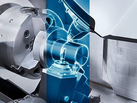
6-sided machining with Turn & Mill Spindle compactMASTER
Highlights

High productivity
- The compactMASTER, the world’s shortest tool spindle in its class (350 mm), ensures a wide machining envelop to increase productivity
- Wide range of machining area with the X-axis stroke of 675 mm (-125 - +550 mm) and the Y-axis 300 mm (±150 mm)
- Y-axis stroke of ±40 mm of Turret 2 expands the machining range
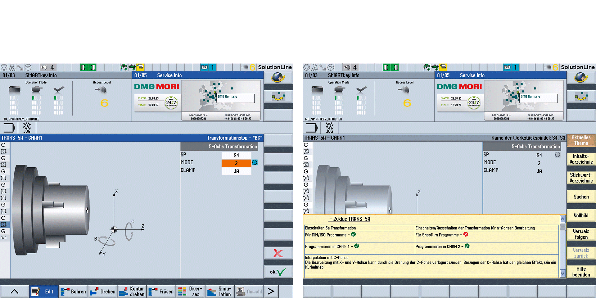
Simultaneous 5-axis machining
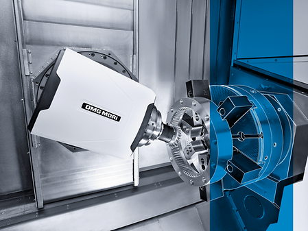
- Simultaneous 5-axis machining with the Direct Drive Motor (DDM) on the B-axis
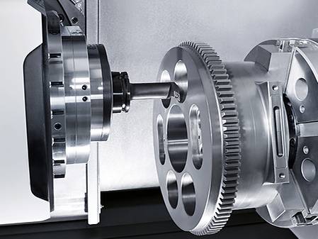
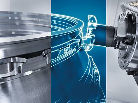
- 6-face machining is available with Spindle 2 to complete the machining of components on one machine
High precision
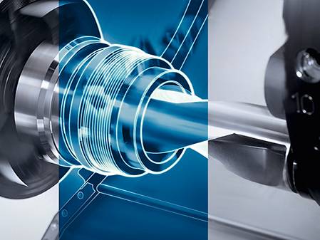
- Cooling oil circulation in spindle motors and ball screws controls thermal displacement and achieves highly accurate machining
Energy-saving
- Energy-saving Setting and Visualization of Energy-saving Effect

")


Control & Software
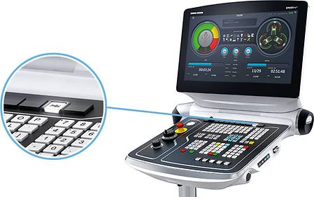
Experience the speed of digital transformation (DX)
Revolutionize your operations, unlock new opportunities, increase efficiency and promote sustainability by reducing power consumption – while gaining a strong competitive advantage.

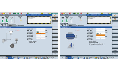
- DMG MORI specific user interface optimized for vertical screen orientation
- Fully customizable flexible display with up to 10 windows and arrangement in window sets
- 3D collision control and machining simulation
- Comprehensive machining cycles
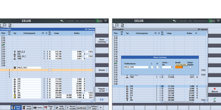
- Tool Management System

- DMG MORI specific user interface
- Extensive machining cycles
- Flexible display through 6-window display and arrangement in window sets
- 3D collision control and machining simulation
- Extensive machining cycles
- Tool Management System

- DMG MORI specific user interface
- Extensive machining cycles
- Flexible display through 6-window display and arrangement in window sets
- 3D collision control and machining simulation
- Extensive machining cycles
- Tool Management System
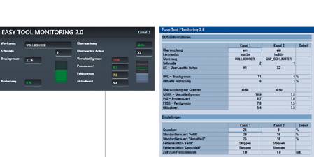
- Prevention of damage due to tool breakage or tool overload
- Sensorless with automated learning of load limits
- For turning, milling and drilling (up to 3 mm diameter)
- NEW: User interface on CELOS SideScreen
- NEW: Powerful algorithm for efficient monitoring after the first workpiece
- Protection Package: Perfect supplement to MPC Lathes. Price advantage (approx. 40%)
- Save the monitoring limits for each tool and every cutting edge in the program

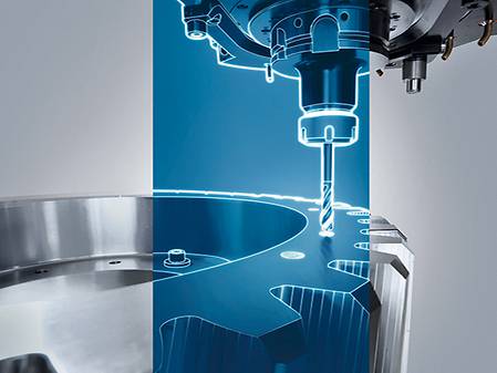
- Free form surfaces by 5-axis interpolation on the main and counter spindle
- Turning and milling with interpolated B-axis
- Programming the 5-axis movements via customer CAD / CAM systems
- An intellegent Look-ahead function for a continuous process
- High surface quality and transitions in combination with thermal compensation
- Machines calibrated to half tolerance
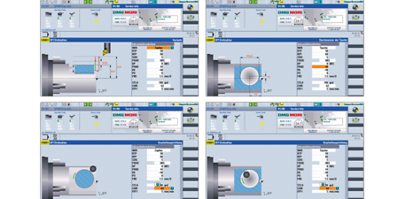
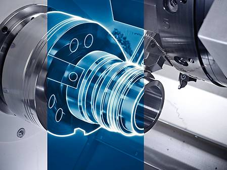
- With interpolation turning, the tool cutter follows a circular movement, where the cutter is always oriented towards the center Of the circle.
- Possible for external and internal machining
- Synchronization and tool path controlled by the cycle
- NEW: in version 2.0 complex turning contours are possible (currently only available on the DMU 50, other machine types will follow)
- Easy manufacturing of sealing surfaces where milling operation might not be possible.
- Complete component processing in one clamping possible
- Reduced investment costs for tools

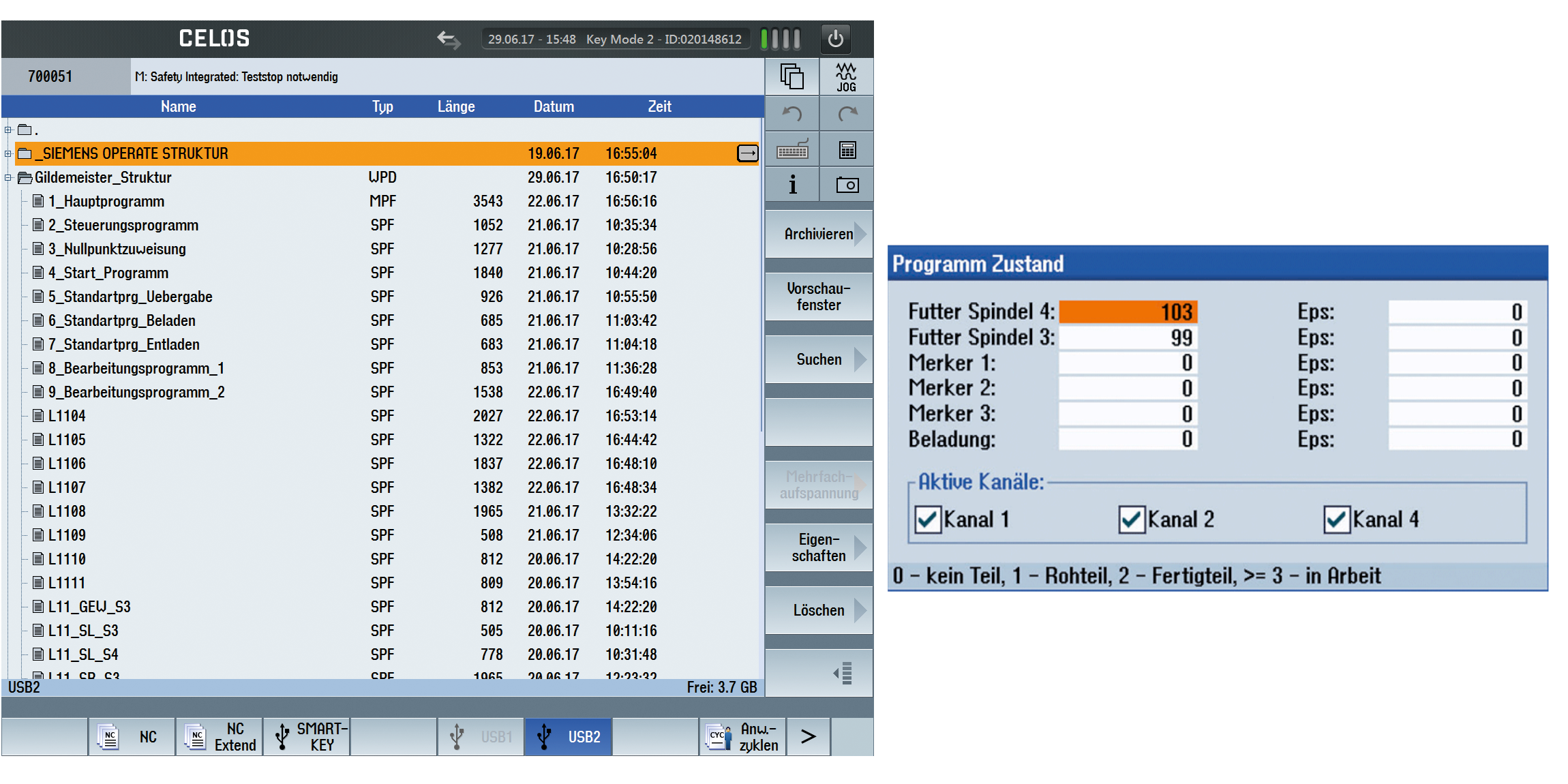
- In combination with the Gildemeister structure programming, A safe and fast reboot of the machining program after an interruption
- Easy program operation especially with multiple spindles or tool magazine
- Displays the process status of the workpiece
- Display of the detailed status on the controller
- Enter remarks automatically by the GILDEMEISTER structure programming.
- Safe re-entry into the program by the press of a button instead of searching for a specific block.
- Structured approach with more than 20 standard programs and more than 200 processing variants incl. automation (bar processing, robot / portal loading, ...)
- Display of the program status with additional markers (EPS) for the sub-programs.
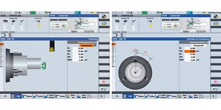
- Superposition of the turning movement by additional X- and Y-traverses
- Applicable for turning and milling
- Eccentric geometries easy to manufacture
- Exact axis coupling and synchronization in the background
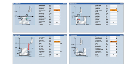
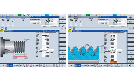
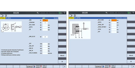
- NEW: On-Point Threading - Position oriented thread production
- Free definition of contours, pitches and gears possible
- Creation of large transmission threads, which can not be manufactured by simple thread chasing
- Trapezoidal, buttress and knuckle thread easily programmable at the machine
- Screw conveyor with any profile geometry
- Ball screw nut with cross holes simple to realize

Highlights
- Producing profiles with undercut due to the profile splitting option.
- Applying standard tools and tool holder for left and right sided machining of the flanks
- Surface quality of Ra 0,3 an CrNi-Alloys possible
- Solutions for a safe process and for the efficient use of important machining steps
- Applications: cone cleaning, tool data monitoring, safe withdrawal movement, tapping, deep hole drilling, external thread and spigot milling, internal thread and circular milling, reverse countersink cycle
- 12 stored machining strategies for stock removal, deep hole drilling, Pocket milling machines*
- Runtime optimization according to individual application
- Safe retraction after program break
- Tool data monitoring

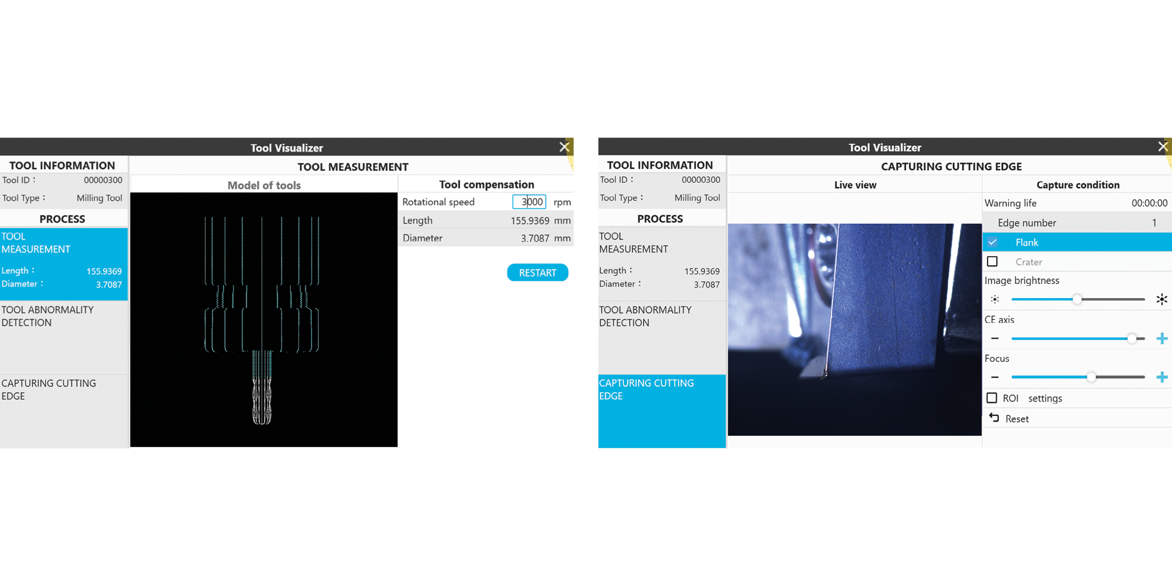
- Non-contact measurement with the integrated and protected camera system
- Automatic measurement of the tools
- Support for fine correction of tool dimensions
- 3D visualization of the measured tools
- Detection of tool abrasion
- Time saving due to the fully integrated measuring system
- Automatic tool correction possible through offset data
- High-resolution camera image for detection of tool damage and abrasion without having to remove the tool
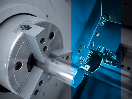
- Perfect combination of 6-sided complete machining and tailstock function
- Automatically load and unload a tailstock centre into the chuck of the main spindle or counter spindle via the milling spindle and into the mgazine
- Support of long and slender workpieces on the main spindle thanks to the synchronous counter spindle tip
- Higher component accuracy due to automatic change without opening the door (heat flow constant)
- Position-locking the spindle with the tip leads to increased process safety


- Residual unbalance-based calculation of the permissible tool speed limit in the HMI
- Continuous monitoring and automatic registration of all limit value violations during machining
- Export function of all registered events in tabular form
- High transparency and sensitivity with regard to tool balancing due to simple operation
- Improved dimensional accuracy, surface quality and reduced tool wear due to the consistent use of balanced tools


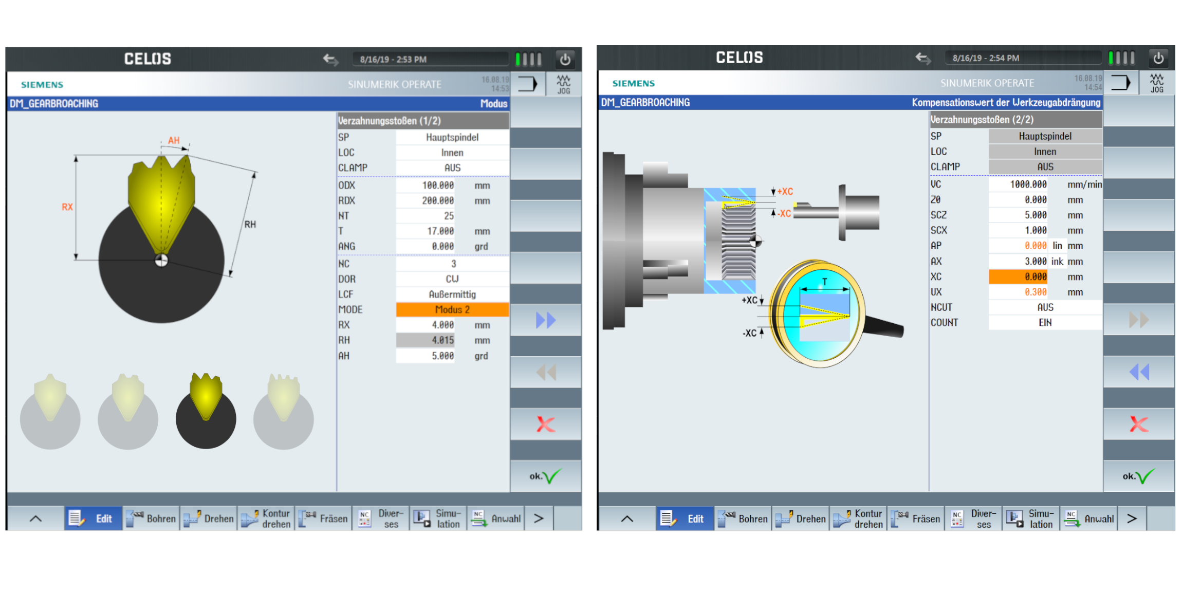
- Broaching of internal and external splines with dialogue guided programming
- One-Tooth up to 4-theeth cutting tools with clear tool definition for easy setup.
- Compensation parameters for tool holder deviation in X-direction
- Fast process setup with safer programming
- High flexibility while process adaption and corrections
- Internal and external gears up to module 4*
* on CTX beta TC up to Module 2 I on CTX gamma TC up to Module 4 I depending on workpiece and cutting tool dimensions

- Producing high precision oval and und polygon geometries with grinding – tolerance class IT5*
- Easy parametrized definition of the geometries based on DIN 32711
- Perfect complement to technology cycle Polygon- / Oval-Turning
* as extension of the grinding technology cycle
- New machining opportunities for more innovations on the part – e.g. shaft-hub connections.
- Position-oriented polygon and oval geometries due to 6-sided complete machining advantages


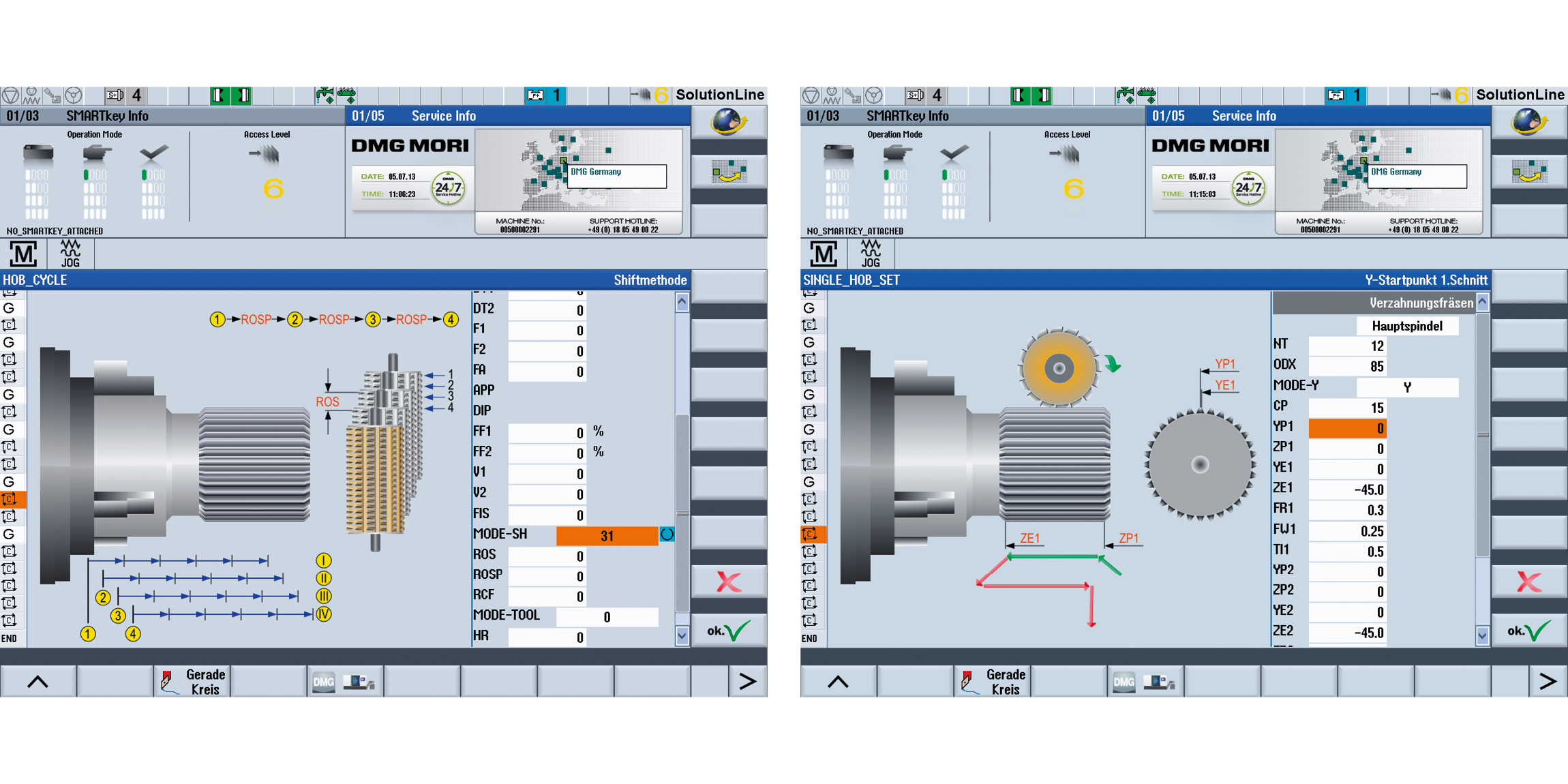
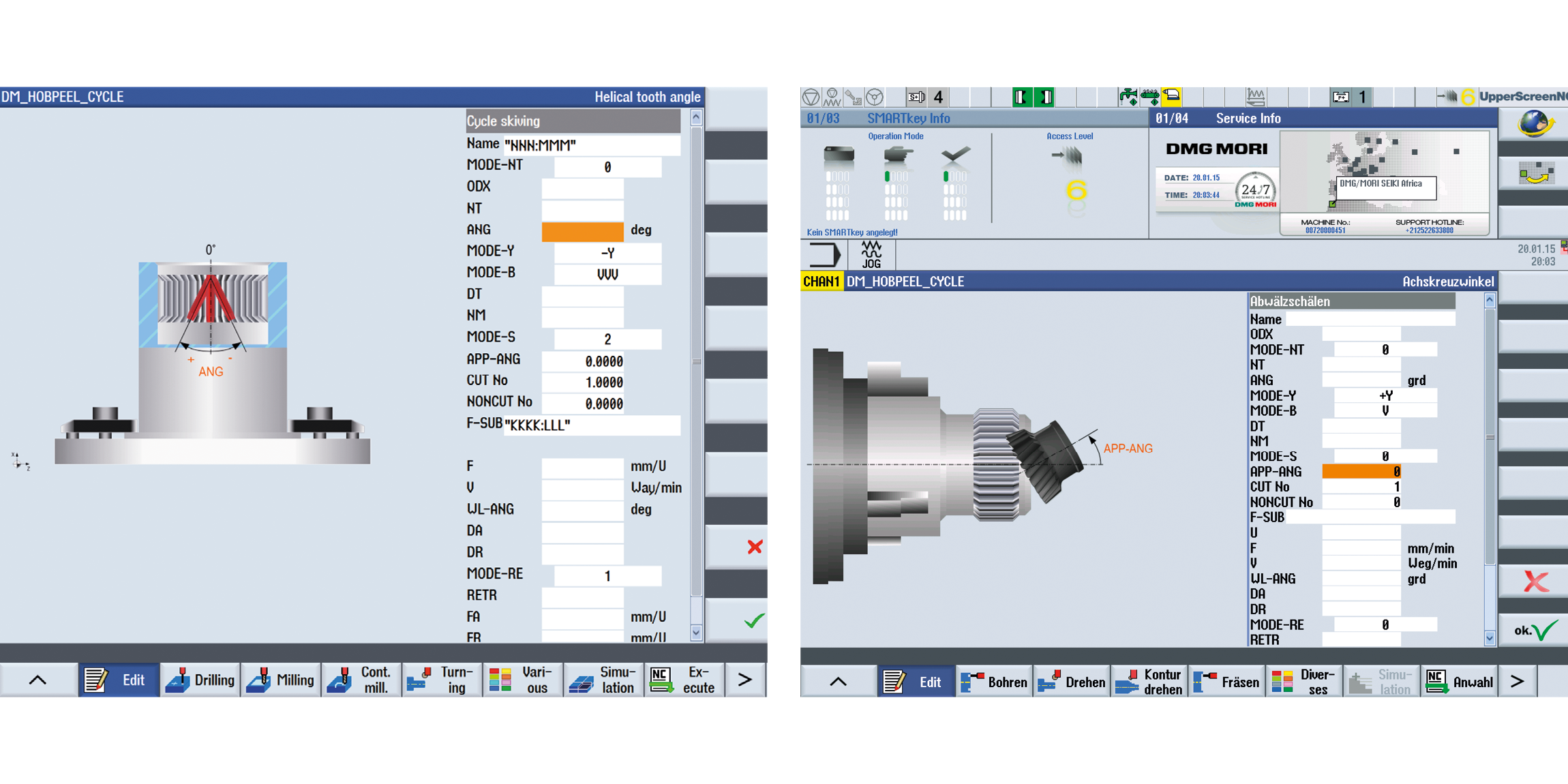
- Programming of the gearing parameters via dialog input
- For spur gear, helical gear and worm gear
- Gear cutters and disk cutters can be used
- Maximized tool life by shifting of the cutter
- Achievable quality ≤ DIN 7
- Gear profile modifications easy to handle
- Use of regrinded tools
- Error prevention by monitoring (e. g. wrong axis cross angle, or wrong turning speed, or turning direction)
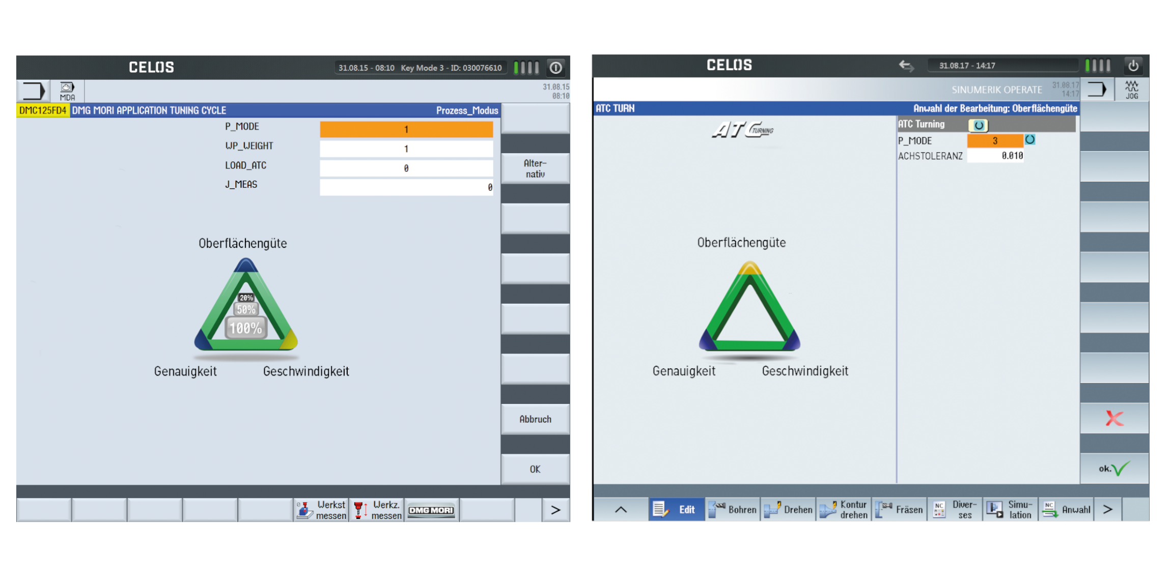
- Process-oriented adjustment of the feed rate n relation to the table loading
- Minimization of machining time with maximization of the component quality
- NEW: Now also available for CTX TC. Ideal machining result with the highest machine dynamics*
*without consideration of feed weight
- User friendly setting of the machine dynamics with included DMG MORI knowhow
- Time saving in roughing
- High surface finish during finishing

- Easy handling of non-circular parts
- Intuitive user interface for polygons / oval turning
- Making the required geometries with possibilities of simple fine-tuning
- Possiblity of fine tuning of the geometric parameters (long / short Semi-axis and bearing angle)
- Machining can be combined with main spindle or counter spindle


- Centring tip mounted on the turret
- Centring tip data is saved directly in the tool memory
- For fixed and spring-loaded centring tips

- Easy operation for positioning the centring tip
- Position-locking the turret leads to increased process safety
- Pressing force of the tip is variable, programmable and monitorable
- Productive complete processing
- Cost-effective gear cutting on standard machine with standard tools
- Flexible for different gear geometries
- Quality inspection in the process
- Program creation based on blank drawings and gear data
- Optimization of workpiece orientation e.g. after heat treatment
- Interface for coordinate measuring device (Klingenberg, Leitz, Zeiss)
Turning
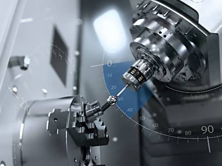
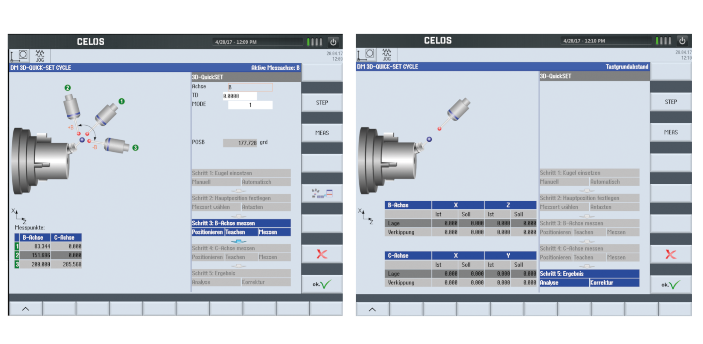
- Measurement and correction of the position of turning and Pivot axes (C4, C3, B)
- Sag compensation possible
- Can be used in combination with standard probes from customers (recommended Renishaw, Blum)
Milling
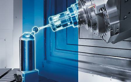
- Toolkit for checking and correcting the kinematic accuracy of 4- and 5-axis machine configuration
- All head variations and table axes
- Reliable re-calibration of the machine before a highly precise processing
- Continuous documentation of machine accuracy
- No rejected parts due to unknown Geometric-deviations
- Periodic recalibration of the machine with comprehensive documentation
- Highest kinematic accuracy in self-regulation
- Integrated clamping force calculator according to VDI 3306
- Intuitive calculation of the minimum and clamping forces based on the used machining parameters
- Comprehensive package for internal and external clamping with 3 to 8 jaws for turning, milling and drilling
- Avoidance of component deformation due to unknowingly excessive clamping force
- Increased clamping safety
- Faster set-up and safe clamping in combination with iJAW (DMQP RÖHM)

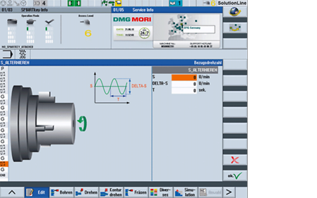
- Oscillating movement of the feed axis results in air cutting, which leads to effective chip size reduction
- For external longitudinal turning of internal and external diameters, facing, drilling and grooving*
- Integrated safety function checks plausibility of parameter entries
* For inclined surfaces, a step pattern results because the feed can only be oscillated in one axis at a time.

- The chip length can be practically determined by the cycle and is independent of the material
- No more process interruptions, as chip balls are avoided
- Easy setting on the HMI with high operating safety


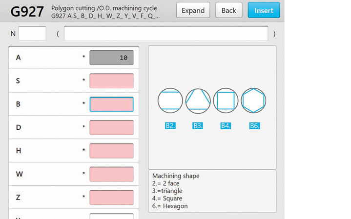
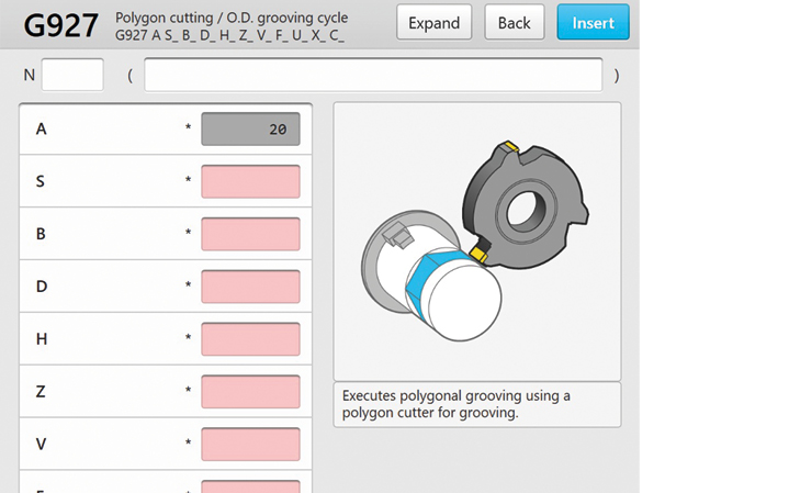
- Milling of oval and polygonal geometries
- Machining of excentric face polygons possible
- Simple selection of suitable machining strategies
- Simple parametric definition of the shaft-hub connection according to DIN 32711 and DIN 32712
- Enable the machining of small workpieces or those made of long-chipping materials. The perfect complement to Polygon / Oval-Turning.


- Machining also on machines without Y-axis
- Highly productive without milling the individual surfaces
- Dialog-guided programming thanks to the technology cycle
- Productivity especially for small components
- Chamfering possible in the same process
- Simple and fast programming minimizes errors

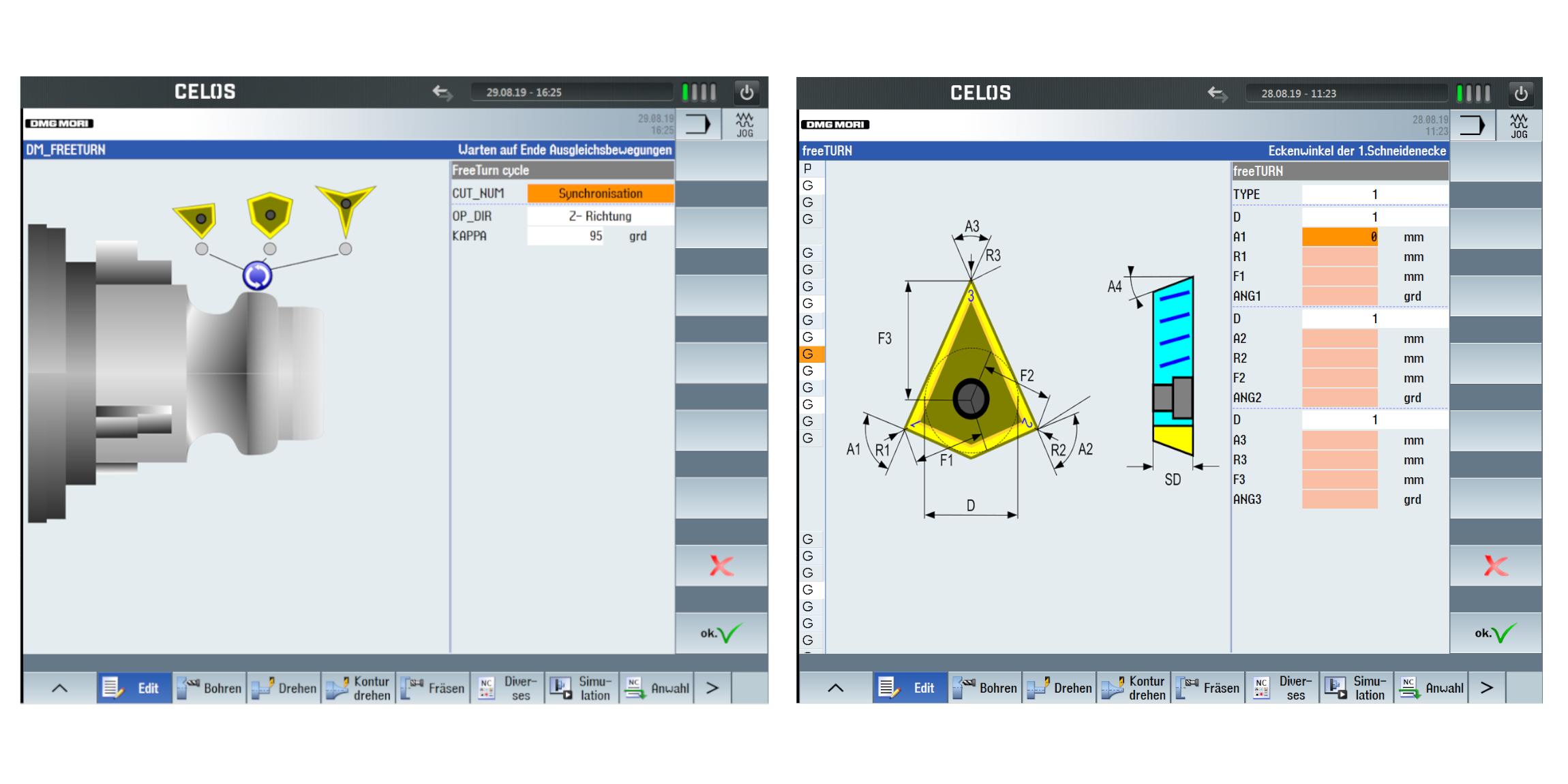
- For shop-floor programming with easier integration in the NC-program.
- Easy tool definition in for the NC-program due to the integrated tool library
- Possibility to define the adjusting angle (kappa) for each cutting edge and each operation to achieve the best machining results
* Simultaneous movement of Kappa must be programmed with CAM
- Possible saving of different tools and related tool changing time
- For roughing and finishing, profile turning, external cylindrical and face turning operations with optimized cutting force direction
- Easy to operate through three parameters and without additional sensors
- Avoiding vibrations by means adaptation of the speed
- Application for the main spindle and counter spindle, or for milling machines with FD tables with Direct Drive
- No manual intervention by the operator
- Identical repeatability for all components
- Increased process safety for special applications by avoiding vibrations. example, When using long thin drills or for milling parts with critical clamping

- Application especially for multi-channel machines for time analysis of the production process and as a basis for the cycle time optimization
- Individual zoom in to view minute details for cycle time optimization
- Histogram up to three channels
- Provides the basis for cycle time optimization by graphical inputs
- Save / Load the recorded data to compare individual optimized steps

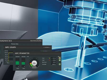
- Vibration monitoring in the process
- Rapid shutdown in case of a crash
- Manual retraction even in swiveled machining plane
- NEW: Torque monitoring
- New: Recommended with Protection Package for CTX TC machines
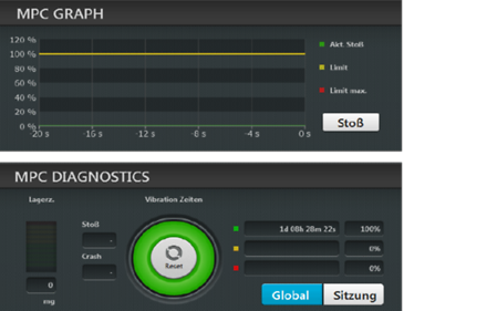
- Avoiding tool breakage
- Increase in machine availability
- Damage reduction
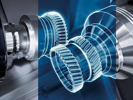
- Straight and helical external or internal spur gears and splines
- Arrow teeth with tooth offset Turn-mill machines
- Ball-shaped toothing by mathematical transformation of the 6th virtual axis
- Internal toothing without angular head possible
- Short processing times, 10 x faster than shaping
- Synchronization and tool path controlled by the Cycle
- By pushing the associated key the X- axis and the Y-axis travel to the positive end-positions for external machining
- Ideally suited to prepare the work space for set-up and alternatively also as an emergency rescue function.
- Easy operation when setting up multi - channel machinery
- Possibilty of a fast response during external machining as a rescue function

- Hydraulically operated steady rest to support long and slim components
- Expansion of the possibility of using multi-channel machines
- The cycle allows both approaching to and retraction from the steady rest

- Hydraulically operated steady rest in the tool table
- Position-locking the turret leads to increased process safety
- Fix the steady rest position, to position and shape tolerances to comply with the program after reboot
- Efficient use of multi-tip turning tools with more than one cutting edge on turn & mill
- Several "sister tools" on one main tool holder
- Reduction of tool change times
- Saves tool magazine space
Service & Training
Comprehensive carefree service and training for your production
Take advantage of our full-service offering and hands-on training to maximize machine performance and minimize downtime. With comprehensive maintenance packages, original spare parts and tailored training programs, we can take your production and your team to the next level.